L2A Assembly Guide
Damaged or Missing Parts All kits and parts are checked before being shipped to you. If something arrives damaged or if your kit is missing a part, please open a support ticket to inquire about a replacement. Missing parts will be replaced at our expense. Damaged parts should be returned for verification. If the part shows signs of use beyond what was necessary to determine that it was damaged, DIY Recording Equipment, LLC reserves the right not to replace the part.
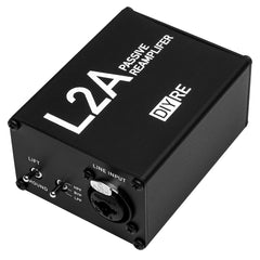
Thank you for purchasing a L2A Passive Re-Amplifier Kit!
If this is your first DIY project ever, we recommend reading our Getting Started Guide.

Required Tools
You'll need the tools below to complete this build.

Soldering Iron
We recommend an adjustable-temperature station, such as the $40 Weller WLC100.

Solder
You can use 60/40 "leaded" solder or lead-free. We recommend 60/40 because it flows better and is easier for beginners to use.
Phillips Head Screwdriver
A #1 Phillips head screwdriver.

Flat Head Srewdriver
A small flat head screwdriver.
Wire Cutters
You'll need a pair of good "snips" for cutting of the excess leads after soldering.
Optional Tools
These tools aren't strictly necessary but can make your build a bit easier.

Multi-Meter
If you find the color bands on resistors a bit hard to read, you can use a meter to sort them with absolute confidence.
Desoldering Pump
If you accidentally solder something in the wrong place, a desoldering pump can save the day.
Assembling the L2A

Identify Parts
- L2A Case
- Foam pad
- L2A PCB
- Edcor PC10K/10K transformer
- Front and back panels
- Input XLR jack
- Output 1/4" jack
- Potentiometer
- Toggle switch
- Knob and set screw
- 15k resistor
- 15x screws (some extras, because they're easy to drop!)

Bend Resistor Leads
Bend the leads of the resistor near the body to make it easy to insert into the PCB.

Place Resistor
Place the resistor through the pads marked "R1 / 15k" on the PCB. Bend the leads against the bottom of the PCB as shown so that the resistor stays in place during soldering.
Notes: Since resistors don't have any polarity, it doesn't matter which way the leads are facing. And, since this resistor will not be letting off significant heat, you can place the body flush against the PCB.

Solder Resistor
Solder the resistor to the PCB. Here are a couple good soldering practices to observe:
- Heat the pad and lead together for 2-3 seconds before applying solder
- Apply just enough solder to cover the entirety of the pad, so that no gold is showing through
- Leave the iron in place while you are adding solder and for 1-2 seconds after
- The entire soldering process should take 5-8 seconds
- Allow the solder joint to cool for about 20 seconds before soldering another lead of the same component

Place Output Jack
Place the 1/4" output jack in the area on the PCB labeled "J2 / OUTPUT." To keep the jack in place, simply hold it while flipping the whole assembly over. Or, alternatively, bend the leads back with a small flat-head screwdriver as shown.

Solder Output Jack

Place and Solder Potentiometer
Place the pot in the position marked "VR1 / Volume." Because of the pot's snap-in mounting pins, there's no need to bend the leads. Solder all five pins of the pot.

Place Transformer
Place the transformer on the PCB in the area marked "X1 / 10K/10K." Note that there's a small notch in the plastic near pin 1. Line this notch up with the corresponding one on the PCB.

Solder Transformer

Place & Solder Input Jack
Place the XLR jack in the "J1 / Balanced INPUT" position on the PCB. Lay the jack on it's back with the PCB lying on top of it to solder.
Solder the three metal pins of the XLR jack. Don't solder the two plastic mounting pins.

Place Switch

Attach Front Panel and Solder Switch
Attach the front panel over the switch and XLR jack, and screw the panel to the XLR jack. Since these screws are cutting their own threads in the aluminum, you'll feel a healthy amount of resistance the first time you put them in.
Make sure that the switch is sitting nicely in the front panel and then solder the leads of the switch to the PCB.

Trim Excess Leads
Trim away the excess pins and leads with a wire cutter. Cut each lead as close to the solder joint as possible, without compromising the joints themselves. You don't need to clip the pot's mounting tabs.

Slide PCB into Case
Slide the assembled PCB into the lower channel in the chassis. The front panel should be on the side of the case nearest the "L" in "L2A."

Screw in Panels
Screw in the eight remaining mounting screws.
It's a good idea to install all four screws on one panel loosely before tightening each one.

Attach Knob and Jack Nut & Washer
Place the knob over the shaft of the pot, line up the set screw with the flat side of the shaft, and fasten the set screw. The set screw may require a flat-head screwdriver or 1.5mm / 1/16" hex key.
Place the washer for the output jack on the bushing, then thread the nut onto the bushing. You can simply tighten the nut with your fingers.

Apply Foam Sticker
Apply the neoprene foam to the bottom of the case.
Using the L2A

Operation
The L2A (LINE2AMP) is a passive re-amplifier. It provides a transformer-balanced, low-impedance, line input and unbalanced, high-impedance, instrument output.
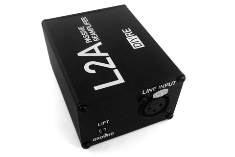
Input
The L2A accepts a balanced, line-level input via an XLR jack. The ground lift switch can be used to eliminate ground-related noise and hum. Typically, the switch should be left in the "lift" position.
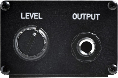
Output
The unbalanced, guitar-level signal exits the L2A via a 1/4" TS jack. The output can be sent to any unbalanced input, such as a guitar amp or pedal.
The Output control can be used to attenuate (but not boost) the L2A's output volume. When the control is set completely clockwise there is no attenuation (unity gain).
Final Checks
Before you wrap up, check the following things:
-
Resistors: Do all of the resistor positions correspond the chart and/or sorting sheet?
-
Soldering: Is every solder joint shiny and clean? If one is cloudy or misshapen, try reheating it for 8 seconds and adding a tiny bit more solder.
-
Trimming: Are all of the excess leads trimmed down as close to the joint as possible?
All good? Congrats on finishing your build! Have a question or problem? Drop us a line.
Help Us Improve
1
2
3
4
5
6
7
8
9
10